



Hi all,
It was actually Graeme Smith from Australia that started this whole story back in the late 90’s, and much of the credit should go to his foresight.
I had been an ardent RC model helicopter enthusiast for several years and read a series of articles in a RC helicopter magazine by ventriloquist Jeff Dunham about building a Rotorway kit. I was totally hooked.
I purchased a Rotorway EXEC 90 kit in 1994, one of the first in Australia. A few years later Graeme was appointed as the new Australian distributor (not sure of the date but must have been around 1996), and as many of you would know, Graeme has for many decades been involved in experimental classification helicopters and has researched and implemented many new innovations and upgrades, particularly with the RotorWay helicopters.
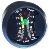
Westach produce some great cost effective gauges for experimental and amateur built aircraft and a lot of their gauges were supplied in the RW kits. , However their analog rotortach always had some noticeable shortcomings, such has poor needle tracking, poor RPM accuracy, the need for calibration before use, drift with temperature, and it was often affected when the radio transmit button was pressed. As an person that grew up and learnt electronics in the 60’s and 70’s analog era I would be the first to admit that analog circuitry is not an ideal or easy solution for this type of application that demands high repeatable accuracy and negligible affect from environmental conditions. But digital solutions were less readily available in the 80’s and 90’s .
The original Westberg tacho is a pure analog device and as such is obviously very susceptible to RF interference. Whilst shielded cables and using correct grounding techniques can sometimes help alleviate these problems, a digital tacho has a very much higher level of immunity to this problem. A slight amount of RF induced onto the signal cables, or directly radiated through the plastic tacho case (only a few millivolts of interference) onto the PCB is likely to affect the reading of an analog tacho. With a digital device, a small amount of superimposed RF signal will have no effect until its amplitude comes close to the amplitude of the digital signal (about 3 - 4 volts, ie. a thousand times higher)
Also the gauge readings would vary with temperature. Owners may experiences temp changes from -40 to +100F. Whilst in Australia we don't experience temperature changes of that magnitude, and the digital tacho there is (by definition) no drift with temperature on a digital device. Temperature drift is an "analog thing" and can only occur in analog circuits. A digital tacho is all digital except where it interfaces to the meter movement where the digital signal is converted back to analog. ie 98% of the device is digital. The analog components that are used to drive the meter operate at unity gain and hence will have negligible temperature drift.
A digital tacho is also inherently very precise (using mathematical algorithms) and hence capable of very accurate tracking of rotor and engine speed.
Knowing that I owned an electronics design and manufacturing company ( mainly working at that time in the industrial and oil/coal exploration fields), and was also a RotorWay owner, around 1998 he approached me to see if I was interested in designing a new improved rotortach that would overcome the shortfalls in the existing unit.
We decided that the best option would be for us to develop completely new circuitry based on digital microprocessor electronics to replace the original analog circuit board, but retain the existing case and meter movements etc. That way we could offer cost effective upgrades to anyone with an existing rotortach, by simply replacing the circuit board, and without the need and high costs involved in a total product redesign and associated plastic injection moldings for new case components etc.
In 1999, we had a successful prototype PCB working. Even though we could design a microcontroller digital circuit with optically isolate engine and rotor signal inputs with crystal controlled RPM accuracy that would never require customer calibration (eliminating the need for the optical rotor blade RPM measuring tool that was supplied with the RW kit) we did come a bit unstuck with the meter movements - as you will soon see.
For the original prototype unit we carefully “characterised” / calibrated the engine and rotor meters such that we knew the exact relationship of meter voltage to RPM reading on the dial. And this relationship in the form of a digital look-up table was programed in to the code that went in to the microcontroller. So, all good, and the result was perfect. Absolute accuracy and precise tracking of engine and rotor display over the full range – just what we were after.
However, the meter movements themselves are inherently analog devices and as such every individual meter movement is just slightly different in its sensitivity. We hadn’t actually considered that at the time (silly us!).
So, when we assembled our second prototype for testing, with another set of new meter movements, the result was disappointing as the meter readings were both slightly out in accuracy, and they did not track perfectly.
What this meant was that every tacho we were to manufacture would clearly require it’s own individual custom calibration look up table that would need to be downloaded in to the firmware when it was manufactured. At the time that was not good news. Every tacho manufactured would indeed need to be unique – and that hasn’t changed to this date. Hence the important serial number on the back of every tacho, and this relates back to its own manufacturing file with it’s unique calibration data. For every tacho that has been manufactured since 1999, we have all it’s details on file in case we ever need to refer to it for repairs etc.
However fortunately we found a way to simplify this onerous task and speed up the measuring and calibrating of every individual meter movement. We developed a separate program (using MATLAB) that could extrapolate and generate a full look up table covering the 45% to 114% dial range based on twelve spot measurements. It still takes time to do each one but the end result is perfect accuracy and tracking of both needles.
And that is how we came to start modifying and upgrading RW rotortachs with an effective digital solution.
Sadly I do not have a photo of the original digital circuit board. But soon after releasing the new digital RW upgrade we got approached by Russ Gerrish around 2002 who had heard about our rotortach and was after one to suit the Jet Exec. And that started a whole new interesting chain of developments of the product that continues to this day. That will all be covered in my Part 2 of the story. Attached is a photo of the revised circuit from 1992 that was resigned to suit both the standard RW and also the Jet Exec. That’s 24 years ago! I just can’t believe where all the years have gone.
![[Image: 20260925-183941.jpg]](https://i.ibb.co/WNHM7j01/20260925-183941.jpg)
It was actually Graeme Smith from Australia that started this whole story back in the late 90’s, and much of the credit should go to his foresight.
I had been an ardent RC model helicopter enthusiast for several years and read a series of articles in a RC helicopter magazine by ventriloquist Jeff Dunham about building a Rotorway kit. I was totally hooked.
I purchased a Rotorway EXEC 90 kit in 1994, one of the first in Australia. A few years later Graeme was appointed as the new Australian distributor (not sure of the date but must have been around 1996), and as many of you would know, Graeme has for many decades been involved in experimental classification helicopters and has researched and implemented many new innovations and upgrades, particularly with the RotorWay helicopters.
Westach produce some great cost effective gauges for experimental and amateur built aircraft and a lot of their gauges were supplied in the RW kits. , However their analog rotortach always had some noticeable shortcomings, such has poor needle tracking, poor RPM accuracy, the need for calibration before use, drift with temperature, and it was often affected when the radio transmit button was pressed. As an person that grew up and learnt electronics in the 60’s and 70’s analog era I would be the first to admit that analog circuitry is not an ideal or easy solution for this type of application that demands high repeatable accuracy and negligible affect from environmental conditions. But digital solutions were less readily available in the 80’s and 90’s .
The original Westberg tacho is a pure analog device and as such is obviously very susceptible to RF interference. Whilst shielded cables and using correct grounding techniques can sometimes help alleviate these problems, a digital tacho has a very much higher level of immunity to this problem. A slight amount of RF induced onto the signal cables, or directly radiated through the plastic tacho case (only a few millivolts of interference) onto the PCB is likely to affect the reading of an analog tacho. With a digital device, a small amount of superimposed RF signal will have no effect until its amplitude comes close to the amplitude of the digital signal (about 3 - 4 volts, ie. a thousand times higher)
Also the gauge readings would vary with temperature. Owners may experiences temp changes from -40 to +100F. Whilst in Australia we don't experience temperature changes of that magnitude, and the digital tacho there is (by definition) no drift with temperature on a digital device. Temperature drift is an "analog thing" and can only occur in analog circuits. A digital tacho is all digital except where it interfaces to the meter movement where the digital signal is converted back to analog. ie 98% of the device is digital. The analog components that are used to drive the meter operate at unity gain and hence will have negligible temperature drift.
A digital tacho is also inherently very precise (using mathematical algorithms) and hence capable of very accurate tracking of rotor and engine speed.
Knowing that I owned an electronics design and manufacturing company ( mainly working at that time in the industrial and oil/coal exploration fields), and was also a RotorWay owner, around 1998 he approached me to see if I was interested in designing a new improved rotortach that would overcome the shortfalls in the existing unit.
We decided that the best option would be for us to develop completely new circuitry based on digital microprocessor electronics to replace the original analog circuit board, but retain the existing case and meter movements etc. That way we could offer cost effective upgrades to anyone with an existing rotortach, by simply replacing the circuit board, and without the need and high costs involved in a total product redesign and associated plastic injection moldings for new case components etc.
In 1999, we had a successful prototype PCB working. Even though we could design a microcontroller digital circuit with optically isolate engine and rotor signal inputs with crystal controlled RPM accuracy that would never require customer calibration (eliminating the need for the optical rotor blade RPM measuring tool that was supplied with the RW kit) we did come a bit unstuck with the meter movements - as you will soon see.
For the original prototype unit we carefully “characterised” / calibrated the engine and rotor meters such that we knew the exact relationship of meter voltage to RPM reading on the dial. And this relationship in the form of a digital look-up table was programed in to the code that went in to the microcontroller. So, all good, and the result was perfect. Absolute accuracy and precise tracking of engine and rotor display over the full range – just what we were after.
However, the meter movements themselves are inherently analog devices and as such every individual meter movement is just slightly different in its sensitivity. We hadn’t actually considered that at the time (silly us!).
So, when we assembled our second prototype for testing, with another set of new meter movements, the result was disappointing as the meter readings were both slightly out in accuracy, and they did not track perfectly.
What this meant was that every tacho we were to manufacture would clearly require it’s own individual custom calibration look up table that would need to be downloaded in to the firmware when it was manufactured. At the time that was not good news. Every tacho manufactured would indeed need to be unique – and that hasn’t changed to this date. Hence the important serial number on the back of every tacho, and this relates back to its own manufacturing file with it’s unique calibration data. For every tacho that has been manufactured since 1999, we have all it’s details on file in case we ever need to refer to it for repairs etc.
However fortunately we found a way to simplify this onerous task and speed up the measuring and calibrating of every individual meter movement. We developed a separate program (using MATLAB) that could extrapolate and generate a full look up table covering the 45% to 114% dial range based on twelve spot measurements. It still takes time to do each one but the end result is perfect accuracy and tracking of both needles.
And that is how we came to start modifying and upgrading RW rotortachs with an effective digital solution.
Sadly I do not have a photo of the original digital circuit board. But soon after releasing the new digital RW upgrade we got approached by Russ Gerrish around 2002 who had heard about our rotortach and was after one to suit the Jet Exec. And that started a whole new interesting chain of developments of the product that continues to this day. That will all be covered in my Part 2 of the story. Attached is a photo of the revised circuit from 1992 that was resigned to suit both the standard RW and also the Jet Exec. That’s 24 years ago! I just can’t believe where all the years have gone.